Sources and Outputs
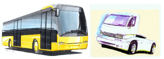
Typically, the sources for further design and engineering work are in the form of initial design sketches together with base build-in dimensions
Výstupem jsou :
-
- data models and layout blueprints
- technological procedure descriptions for parts manufacturers
- parts palleting including pallet construction
- 3D assembly procedure visualizations
Base Concept
Ground issues such as structure, build and technological assembly are addressed.
Eegonomics of the Driver Workplace
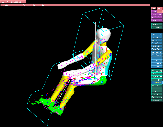
A separate chapter is the conceptual design of the workplace of the bus driver including visual projections of safety and other rules and regulations utilising 3D artefacts.
A Bit on Passenger Coaches
Compared to passenger and cargo vehicle production, passenger coach manufacture entails smaller production series. The classic assembly concept of a frame chassis with the following attachment of body components has long been abandoned. The traditional building process of the body, as predetermined by the technologies of profiles, sheet metal and tin smithing in general however, is being abandoned with some hesitance.
Major pressure factors towards conceptual change include:
- increased technical endowment of contemporary passenger coaches for which it is necessary zo ensure easy service access manufacturing economics pressing on downscaling of labour input in the main assembly
- The contemporary trend, similar to passenger and later cargo vehicle manufacture, is structure division by logical group. This approach avails for greater amount of subgroup pre-assembly away from the main assembly line, today even outside the main manufacturing facility.
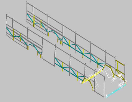
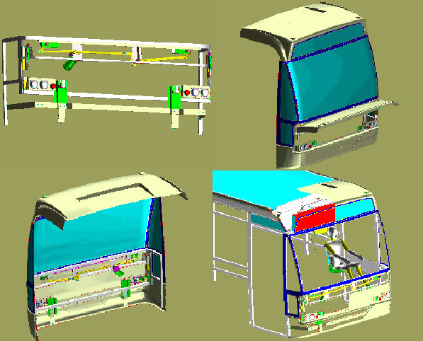
Main Integers
The chief logical integers of the passenger coach body are the sidewalls, the roof and the front and rear frame.
The front and rear frame structures are joined across by the midsection of the body, composed of the lengthwise attaching sidewalls and the roof, whose mutual bonds are the usual places where manufacturing inaccuracies tend to aggregate. Since every dimensional inaccuracy comes to stand out quite clearly on the long and more or less straight sidewall of the coach body, the design of the front and rear framework amounts to somewhat of a designer’s construction jawbreaker.
Approach to problem areas
Greatest inaccuracies occur in places of frame weldmentsAny fiberglass exterior or interior paneling will demand significantly higher manufacturing exactitude.It is therefore advisable to approach the placement of any surface panel mounts with the objective of minimising any reliance on the factual manufactured dimensions of the frameworks.
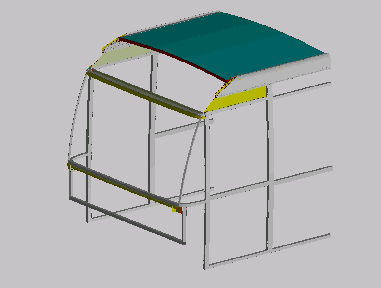
Subgroups
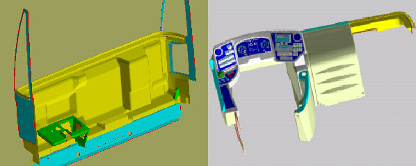
The rear section of the bus can typically be taken care of using a subgroup, which apart from the frame comprises at the same time the inner and outer panels including the hoods and light fixtures. The front is somewhat more complex and demands the use of another subgroup (dashboard equipment, air vent assembly, heating block and air conditioning for the driver, electrical outfit).
Subgroup Assembly

The assembly subgroup layout as delineated here makes it possible for the assembly process of the subgroups to be transferred away from the main manufacturing facility and possibly even abroad. These subgroups then arrive back at the mother plant palette for assembling with the other subgroups. Utilising these constructional/ technological measures at the Berkhof manufacturing plant for example, an increase in main assembly line output could be achieved from original 4 coaches a week to 6 coaches a week, with a possibility open of in the future going up to 8.